// PCB-free prototyping

Stripboard Editor

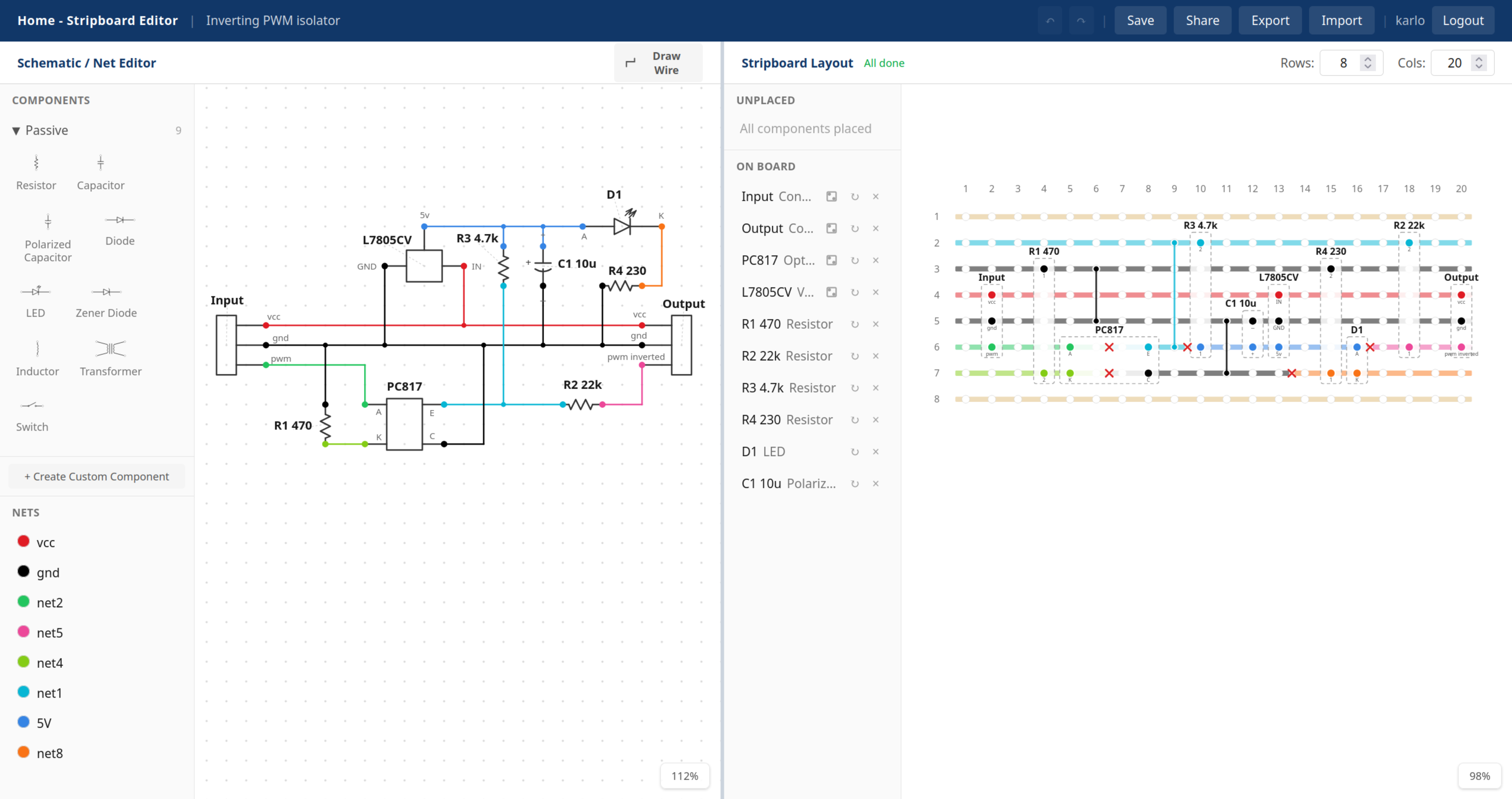
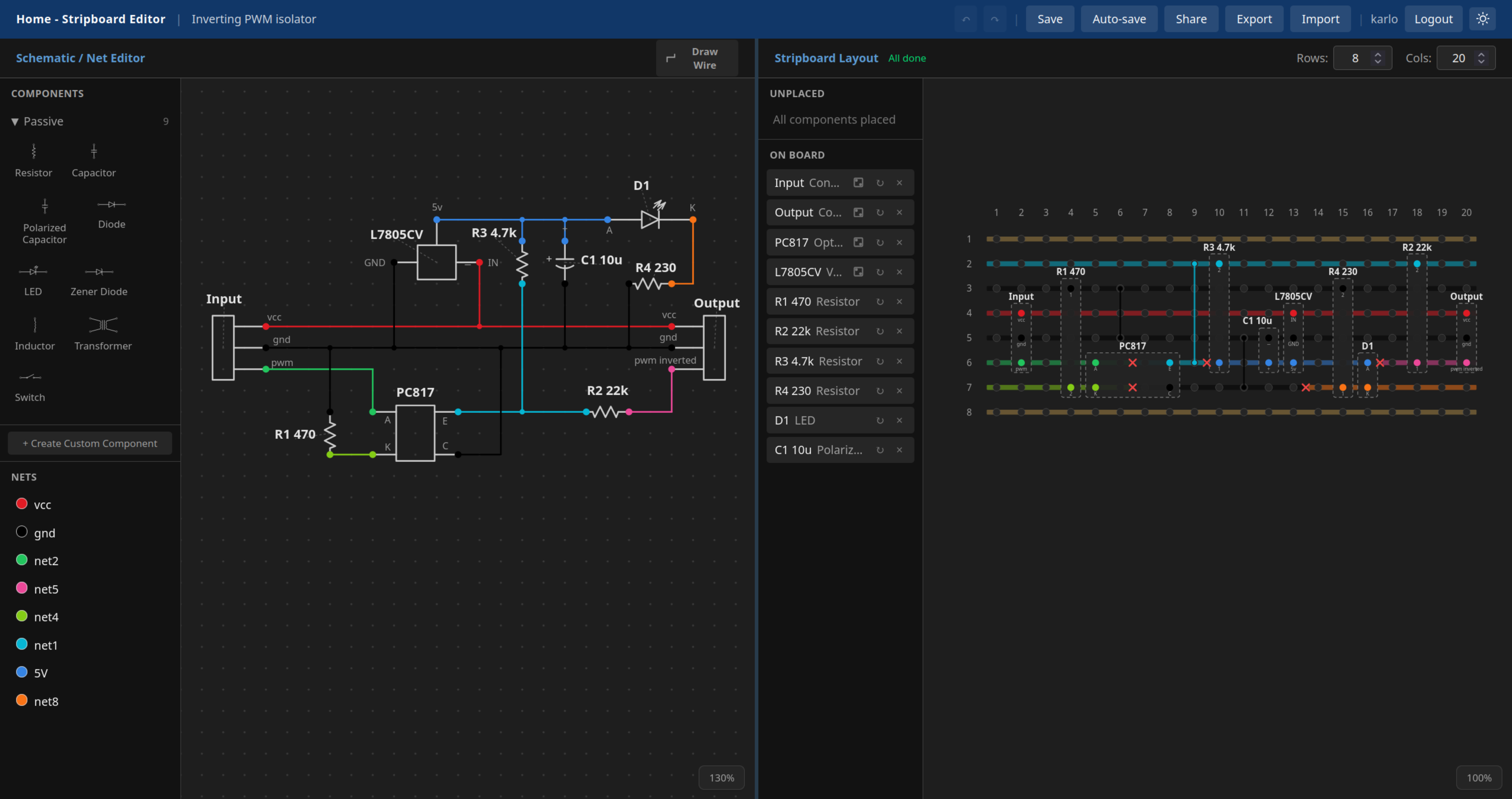
Draw a schematic, place the parts onto a virtual board. The copper strips will take the color of the nets with live conflict detection and an overview of what still needs to be connected. Or hand the circuit to the auto-layout router: it places every part, picks a board size, and works out the strip cuts and link wires for you.

see short guide

Stripboard Editor is a rather new and actively developing project, with new features getting added every now and then.
See what's new and what's coming next →

Have an idea, a bug, or a question? Leave me a message →

Steps

optional

Auto-layout

Skip steps 2 and 3: the router places every part, picks a board size, and works out the cuts and link wires for you. How it works →

001

Draw the schematic

Place components from the symbol library or create your own and wire up the pins to define your nets.

002

Drop onto the board

Drag parts onto the stripboard. Strips colour-code to your nets automatically.

003

Resolve conflicts

Add cuts and link wires. Anything wrong lights up red the moment it happens.

004

Print and build

Print a 1:1 template, lay it on the board, and push parts straight through the paper.

optional

Export a netlist

Take the finished circuit into KiCad or another EDA tool as a netlist and turn it into a real PCB.

what you get

  • Automatic layout router: places every part, sizes the board, and works out the cuts and link wires
  • Schematic editor with a standard symbol library and automatic net detection
  • Live strip colouring with real-time conflict detection
  • Lock the board size or individual parts and let the router design around them
  • Editable IC footprints, custom components, flexible passive leads
  • Printable 1:1 build template with a mirrored cut guide and a BOM
  • KiCad-compatible netlist export to turn a prototype into a PCB
  • JSON export and import, shareable edit and view-only links, full undo history

print and build

Printable 1:1 stripboard build template with a parts list

lay it on the board, push parts through the paper. mirrored cut guide + BOM optional.

Printed placement and cut sheets with a bare stripboard laid on top
print at 1:1
Stripboard with copper tracks cut at the marked holes
cut the tracks
Printed template taped to the board with the first components pushed through the paper
push parts through
Solder side of the finished stripboard
solder the joints
Finished stripboard with every component soldered in place
done. the demo circuit above.
free forever(at least until AI steals my job) · account optional · no ads
a hobby project by Karl Funke (because somehow an editor with live strip coloring like this didnt exist before)